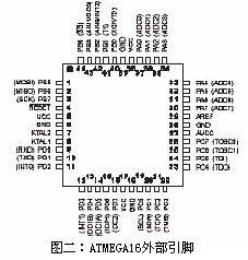
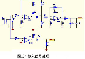
Abstract: The high precision low voltage reactive power compensator based on ATMEGA16 is introduced. The controller uses a digital detection circuit to obtain the phase difference between the grid voltage and current. Based on the principle of reactive power compensation, the controller hardware and software are designed. The system realizes timely compensation and real-time monitoring of the grid power factor in the application, and is suitable for current enterprise users to perform reactive power compensation. Abetted:This article introduces reactive power compensator based on ATMEGA16 controlling with high precision. It measures excess phase of voltage and current by using digital circuit, Based on the reactive compensation theorem, The software and hardware of the controller is deigned.By using the system a timely compensation and real-time monitnring of the power factor in electricity network are possible, It is mainly used to compensate reactive power in present factories and mines. Key words: power factor; reactive power compensation; single chip microcomputer With the development of modern industry, more and more inductive loads are used in the power grid, such as induction motors and transformers. These devices not only consume active power, but also require the grid to provide corresponding reactive power, resulting in a low power factor of the grid. Parallel capacitors in the power grid can reduce the reactive power provided by the power grid to the inductive load, thereby reducing the transmission loss caused by the transmission of reactive power and improving the operating conditions of the power grid. Therefore, the power factor compensation controller has always had a broad application market. The power factor compensation controller introduced in this paper complies with the national standard JB/T9663-1999. The main functions are as follows: (1) Phase sequence automatic identification (2) Voltage, current, power factor sampling and display (3) Overvoltage release, undercurrent blocking, thus protecting the capacitor and avoiding cyclic switching (4) Adopting the principle of first-input first-removal, first-input first-input, and cyclically switching the compensation capacitor (5) All working parameters can be set through the panel buttons, including input threshold, cut-off threshold, over-voltage protection threshold, under-current blocking threshold, switching delay time First, the working principle The phase difference between the current of one line (such as A line) and the voltage of the other two lines (such as BC line) in the sampling three-phase power supply, through a certain operation, obtains the real-time power factor of the current power grid. The power factor is compared with the set input threshold and the cut-off threshold. If the switching threshold is within the entire switching delay time, no action is taken; if it is less than the input threshold, another set of capacitors is input; if it is larger than the cut-off When the threshold is found or the power factor is found to be negative, a set of capacitors that have been placed is cut. After the switching delay time, the comparison and switching are repeated until the current power factor reaches the switching threshold. During the switching process, if the detected voltage is found to be greater than the set overvoltage protection threshold, all the capacitors that have been input are cut off by the group; when the detected voltage exceeds 10% of the set overvoltage protection threshold, then All capacitors that have been placed are removed at one time to protect the capacitor. If the detected current is less than the undercurrent blocking threshold during the switching, the switching action is stopped to avoid the cyclic switching phenomenon of the system. Since there are different wiring methods in the three-phase power supply, different wiring methods have different power factor algorithms. Therefore, we stipulate that the current of the ARC series power factor automatic compensation controller is taken from the A line in the three-phase power supply, and the voltage is taken from The line voltage between BC, and at the same time to reduce the complexity of field wiring, we automatically determine the phase in the program. In the three-phase power supply, we assume that the phase voltages of the three phases are Ua, Ub, and Uc, respectively, and the current of the A line is Ia. Then Ua=Usin(ωt), Ub=Usin(ωt+120o), Uc=Usin(ωt+240o), so that the line voltage between BC is Ubc=Ub-Uc= If the A line load is purely resistive, the A line current Ia is in phase with the A line voltage Ua, and the angle of the Ia leading Ubc is 90o; If the A line load is inductive, the A line current Ia lags the A line voltage Ua angle to be φ (0o ≤ φ ≤ 90o), and the angle of Ia leading Ubc is 90o-φ; If the A line load is capacitive, the A line current Ia leads the A line voltage Ua angle to φ (0o ≤ φ ≤ 90o), and the angle of Ia leading Ubc is 90o + φ In our ARC power factor automatic compensation controller, for the convenience of calculation, our current phase sampling is the second period of voltage sampling, that is, if there is no phase difference Ia, the angle of Ua is 360o. In the actual test, suppose we detect that the angle of Ia lag Ubc is α, according to the above analysis: If 180o < α < 270o, the circuit is a capacitive load, COSφ = COS (270o-α) If α = 270o, the circuit is an inductive load, COSφ=1 If 270o < α < 360o, the circuit is inductive load COSφ = COS (α-270o) In order to facilitate user wiring, if the user connects the voltage Ubc to Ucb, or reverses the input of Ia, according to the above inference, we can also get: If 0o < α < 90o, the circuit is a capacitive load, COSφ = COS (90o-α) If α = 90o, the circuit is an inductive load, COSφ=1 If 90o < α < 180o, the circuit is inductive load COSφ = COS (α-90o) Second, the hardware design The controller's CPU uses ATMEL's ATMEGA16-8L. This chip has a wide operating voltage range (2.7 - 5.5V) and a maximum operating frequency of 8MHz. The chip has 16k bytes of Flash program memory, 512 bytes of EEPROM, 1K words. On-chip SRAM; eight 10-bit ADCs; one programmable serial USART, programmable watchdog timer with independent on-chip oscillator; two 8-bit with independent prescaler and comparator functions Timer/Counter; a 16-bit timer/counter with prescaler, compare function, and capture function. The display chip adopts the keyboard and display special chip CH451S produced by Nanjing Yuheng Company. The CH451S can drive 8 digital tubes, and can directly drive the LED digital tube without external driving, which greatly reduces the size of the printing plate. Mode, only 3 lines (chip select CS, clock CLK, data input DIN), because the system does not use the keyboard function of CH451S, so the DOUT pin of CH451S is not used. Ubc's voltage signal enters the 2mA/2mA isolation converter through the resistor current limit and is divided into two paths. One way enters the analog absolute value processing circuit and sends it to the A/D conversion port ADC0 of the single-chip microcomputer as the voltage display signal, and the other pass through zero comparison. After entering the MCU interrupt port INT0; the same Ia current signal is divided into two channels after 5A/5mA isolation converter, one way into the analog absolute value processing circuit is sent to the A/D conversion port ADC1 of the MCU, as the current display signal, another After a zero comparison, enter the ICP pin of the microcontroller timer gate. Third, the software design Because the accuracy of the voltage and current sampling of the whole system is not high, we directly use the 10-bit A/D of the CPU to perform A/D conversion on the voltage and current signals. The result of the conversion is for display on the one hand, and on the other hand Comparison of overvoltage and undercurrent. We set INT0 to a rising edge to generate an asynchronous interrupt, and ICP is set to a rising edge to trigger an input capture. When INT0 generates an interrupt, the 16-bit counter begins counting at an internal constant frequency until the next interrupt is generated. At the same time of counting, when there is a rising edge pulse on the TCP, the data that has been counted by the 16-bit counter is put into the capture register. When a sampling period ends, the data (N) in the counter is a period base of the external AC signal. The data in the capture register (n) current Ia lags the base of the voltage Ubc, and (n/N)*360o is the angle. According to the above principle, it can be judged whether the voltage lead current or the current lead voltage in the same cycle, and the lead or lag angle can be obtained, and the power factor can be obtained by looking up the data. In order to avoid frequent switching of a certain group in the capacitor bank, the working time of each group of capacitors is balanced to extend the service life of the entire system. We use the principle of priority cut-off for the priority switching of the capacitor, and we have opened up a space in the RAM of the single-chip microcomputer to record the input and cut-off time of each group of capacitors, and then sort them. The longest working time is the priority removal target, and the longest cut-off time is taken as the priority input object. When the load loop current of the three-phase AC is very small, switching oscillation occurs. That is to say, if the control system inputs a set of capacitors, it will cause over-casting. If a group of capacitors is cut off, the input will be insufficient, and the controller will generate repeated switching. In order to avoid this imaginary occurrence, we set the undercurrent lock. When the current value is less than this value, the system will stop the switching action of the capacitor and maintain the capacitor operation. During the working process, if the sampled voltage data is greater than the set overvoltage protection value, the controller will gradually cut off the input capacitor. If it finds that it exceeds 10% of the set protection value, it will cut all the ones at once. The capacitor is put in and the capacitor is protected. The above technology has been applied to the company's ARC power factor automatic compensation control instrument. After testing and running, the system works stably and all the indicators meet the requirements of national standards. It has been put on the market. The article comes from: "Low-voltage electrical appliances", 2006, the 10th issue. Qingdao Beautiful Skin Biotechnoly Co., Ltd , https://www.hafilleresthetic.com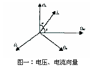
 Usin(ωt-90o)